Modern electrical distribution systems continually face challenges from fault conditions that can damage equipment, interrupt power supplies, and endanger personnel. The protection of these systems requires sophisticated switchgear capable of rapid, reliable, and selective operation to isolate faulty components while maintaining service continuity wherever safely possible. Effective MV switchgear protection serves three critical objectives: limiting thermal, dielectric, and mechanical stresses on equipment; maintaining continuity of supply where safe to do so; and protecting personnel against electrical hazards. To achieve these objectives, the protection system must operate quickly, reliably, and selectively to isolate any faulty component or network section. Essential to this operation is the use of circuit-protective devices such as MV fuses, time-limit fuses, and circuit breakers. Protection relays must be connected to the distribution network by current transformers (CTs) and voltage transformers (VTs), which measure the conditions within the MV network and control the necessary circuit breaker operation. While building services engineers commonly apply ‘high voltage’ (HV) to any voltage above 1000V, MV terminology differentiates these distribution levels from higher transmission voltages.
Understanding Switchgear Components
When electrical faults occur on distribution networks, faulty equipment must be disconnected as quickly and safely as possible to prevent further damage and help stabilize the remainder of the network. Additionally, equipment isolation is necessary for maintenance, and on ring circuit systems, it’s often necessary to vary the open and closed points to make repairs and restore supplies. All ‘switchgear’—defined in BS EN IEC 61936-1 as switching devices and their combination with associated control, measuring, protection, and regulating equipment—must be capable of either closing or opening an electrical circuit.
Circuit Breakers vs. Switches
Circuit breakers and switches share common capabilities: both can safely carry and interrupt their normal rated current, close their contacts onto a fault and carry the fault current for a specified time, and withstand their rated power-frequency system voltage and rated lightning impulse voltage when open. However, the critical difference is that a circuit breaker can both detect and interrupt a short-circuit fault current, whereas a switch can do neither.
Beyond circuit breakers and switches, switchgear encompasses several specialized components:
Switch-fuse: A composite unit containing a switch in which one or more poles also have a series-connected fuse so that fault currents are cleared by fuse operation.
Fuse switch: Unlike switch-fuses, where fuses are fixed, fuse switches incorporate fuses as part of the movable contact set, so during isolation, fuses are also disconnected from the circuit.
Disconnector: Mechanical switches that can carry defined normal and short-circuit current and provide isolation in the open position. They’re used to open and isolate parts of electrical systems when no current flows, allowing safe maintenance access.
Earth switch: A mechanical switch capable of carrying defined short-circuit current, with some able to close onto defined peak short-circuit current and carry that fault current for specified periods.
Circuit Breaker Operation and Timing
The speed of fault current interruption is critical and determined by several timing components. Figure 4 illustrates the timing sequence that determines overall fault-clearing performance. Note how relay pickup time often dominates the total clearing time, emphasizing the importance of fast-acting protective relays in minimizing equipment stress during fault conditions.
The complete interruption process involves:
Opening time: Time between tripping signal and main contact separation (typically 20-30ms)
Arcing time: Time between contact separation and arc extinction under fault conditions (typically 10- 30ms)
Total break time: Sum of opening time and arcing time
Interrupting Capacity
The interrupting or ‘rupturing’ capacity of a circuit breaker, expressed in kA, must align with the fault level at the installation point. For an 11kV system with a fault level of 250 MVA, the required interrupting capacity would be 13.1 kA, calculated using:
Fault level in kA = Fault level in MVA ÷ (√3 × voltage in kV)
Non-Manual Closure and Arc Control
MV circuit breakers can close onto faulty circuits; they’re prohibited from having direct manual closure operation. All circuit breaker ‘closing’ mechanisms require stored energy to operate and ensure full closure before any opening event occurs. Typically, two spring sets are used: one to open contacts and another to close them.
Arc control represents a critical aspect of circuit breaker design. The function involves controlling current flow by changing the impedance of the arc-interrupting medium, thereby reducing current to zero. However, the rate of impedance change is crucial—too slow requires excessive thermal energy absorption, while too rapid leads to excessive restrike voltage generation across breaker contacts, potentially causing insulation damage or flashover.
With alternating current systems, the current naturally passes through two zero-current periods during each cycle. Circuit breakers rely on arc properties to provide synchronized resistance change because, theoretically, at these moments, impedance can change from zero to infinity without producing overvoltages. However, timing errors of even a few milliseconds can still produce dangerous over-voltages.
Circuit Breaker Design Types
At 11kV, two principal circuit breaker designs exist: withdrawable and fixed, with withdrawable types grouped into vertical and horizontal variants for isolation. These are further classified according to their interrupting medium: oil, gas-filled, and vacuum.

Horizontal Isolation
The horizontal withdrawal mechanism shown in Figure 7 offers simpler mechanical systems but requires separate earthing facilities, representing the trade-off between mechanical complexity and functional versatility. Although popular, these designs typically require separate earthing facilities compared to their vertical counterparts.
Fixed Equipment
Circuit Breaker Technologies
Oil Circuit Breakers
Oil Circuit Breakers
The traditional oil circuit breaker design in Figure 9 shows the substantial tank required for oil immersion. While proven and reliable, the physical size and fire risk considerations have driven the industry toward modern alternatives.
Oil circuit breakers (OCBs) are no longer used for new primary switchgear applications but are still occasionally used for secondary switchgear. Understanding their arc interruption mechanism remains important because many remain in use, and as users seek more environmentally acceptable breaker types, OCBs—particularly modern variants with low or minimum oil content—may regain popularity.In the early twentieth century, engineers discovered that immersing circuit breaker contacts in oil aided arc extinction. The arc’s heat decomposes surrounding oil into constituent gases: 70% hydrogen, 22% acetylene, 5% methane, and 3% ethane.
Gas-Insulated Circuit Breakers
Over the past century, many different mediums and switchgear designs have been employed to improve arc extinction and heat dissipation. For many years, SF₆ switchgear was the technology of choice. However, SF₆ has been recognized as an extremely potent greenhouse gas with a global warming potential (GWP)of 23,900 (compared to CO₂’s GWP of 1) and a lifetime of 3,200 years.
The compact ring main unit in Figure 11 illustrates how vacuum circuit breaker technology enables space-efficient designs. The sealed vacuum interrupters eliminate the space and safety concerns associated with oil or gas-filled alternatives. Currently, large numbers of existing SF₆-filled, 11kV ring main units (RMUs) and circuit breakers exist within most secondary DNO and private networks, originally chosen because SF₆ is chemically inert and has both high dielectric strength and good arc extinguishing properties.
The compact ring main unit in Figure 11 illustrates how vacuum circuit breaker technology enables space-efficient designs. The sealed vacuum interrupters eliminate the space and safety concerns associated with oil or gas-filled alternatives. Currently, large numbers of existing SF₆-filled, 11kV ring main units (RMUs) and circuit breakers exist within most secondary DNO and private networks, originally chosen because SF₆ is chemically inert and has both high dielectric strength and good arc extinguishing properties.
Available Alternatives to SF₆
Modern switchgear selection increasingly balances technical performance with environmental responsibility. While SF₆ has historically provided excellent dielectric properties, its significant environmental impact has driven the industry toward alternatives: Novec™ Dielectric: ‘AirPlus’ is a branded mixture of Novec 5110 and dry air, developed from collaboration between 3M and ABB for MV applications, with a GWP of less than 1.g³ (Green Gas for the Grid): Developed by 3M and General Electric, this mixture of Novec 4710 (a fluoronitrile compound) with nitrogen for MV applications has a GWP of 327 at 4% concentration an 462 at 6%.Nuventura Synthetic Air: Produces MV switchgear (available with current ratings up to 1250A) matching typical SF₆ equipment sizes, using synthetic or dry air (80% nitrogen, 20% oxygen).
Vacuum Technology: Many manufacturers, including Eaton, Schneider Electric, ABB, Lucy Electric, and Siemens, have put forward traditional vacuum technology as an SF₆ alternative, with products commercially available for many years.
Vacuum Circuit Breakers
The small contact separation distance and sealed construction minimize both mechanical effort and maintenance requirements while delivering superior dielectric performance. In a VCB, contacts open and close inside a small, sealed vacuum bottle known as the vacuum interrupter. Since contacts break under vacuum, there’s no gas to ionize and conduct the arc. Contact separation distances can therefore remain small, minimizing mechanical effort required and noise generated in opening contacts while ensuring fast contact opening times.
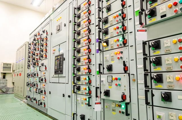
The switchboard installation in Figure 13 demonstrates vacuum technology’s integration advantages. The compact vacuum interrupters enable higher circuit density while maintaining safe working clearances. Excellent dielectric strengths are delivered at maximum negative pressure of one atmosphere (vacuum), whereas achieving the same dielectric strength in gas-filled breakers often requires operation at several atmospheres of pressure.
VCB Operation
As breaker contacts begin to open, an arc forms, causing particles of the hot metal contacts to vaporize. The arc continues until the first current zero occurs in the AC waveform, at which point the arc ceases and metal vapor de-ionizes, cools, and condenses. The arcing period should not exceed half a cycle, and this, coupled with a small contact separation distance (typically 10mm with correspondingly low arc voltage), ensures energy dissipated in the vacuum arc is much less than energy dissipated by oil or gas-filled breaker arcs. Benefits include reduced contact wear, prolonged life, and lower maintenance. Typically, normal vacuum interrupters can handle up to 10,000 switching operations at rated full-load current and up to 100 short circuit interruptions, providing a service life of 20 years without maintenance (note: this applies only to the vacuum bottle; the remainder of the mechanism still requires maintenance).
Current Chopping Considerations
An electric arc in a vacuum is a metallic plasma, whereas gas-filled and oil circuit breakers operate with gaseous plasma. This can cause problems because the number of ions present in the arc depends on the evaporation degree at the electrode surfaces. If the metallic vapor creation rate falls too quickly, the arc may collapse prematurely (before a naturally occurring current zero), causing ‘current chopping’ and inducing large HV transients in the system. Research by BRUSH Switchgear found VCBs consistently capable of current chopping when switching currents of 3-5A (occasionally higher). This theoretically produces very high transient voltage peaks, and in practice, with test transformers, observed over-voltage values were 30-35kV peak when switching steady-state magnetization currents and up to 50kV peak when switching in-rush currents.
Several mitigation methods exist: where transformers are separated from switchgear by cable length, additional cable capacitance may sufficiently reduce peak over-voltages; surge arrestors or surge capacitors can be added close to transformer terminals; or vacuum breakers with low current chopping levels can be used. In most situations, manufacturer advice should be sought.